Main concept
This prototype is based on the periodic compression of an "ambu" that can be used both for invasive ventilation (only in a hospital environment) and for non-invasive ventilation using a mask. Figure 4 shows a typical ambu available on the market.

Figure 4 - Typical ambu bag available in the market
The manual use of ambu bags as a support for ventilation is clinically consistent [8] and is increasing in patients with COVID-19 due to the lack of respirators.
There are several initiatives underway to automate the use of ambu bags for this purpose [9] [10] [11] [12] [13].
By controlling the compression of an ambu, the three most basic ventilation parameters can be controlled:
• The Tidal Volume (TV): proportional to the distance the ambu bag is compressed.
• The respiratory rate (RR): the exact amount of times the ambu bag is compressed per minute.
• The time of inspiration (TI): the time spent to compress the ambu bag in each cycle.
In the current device, the ambu bag is compressed by a linear actuator based on a stepper motor. A linear actuator is a device that develops a force and movement through a straight line using a stepper motor as a rotary energy source.
Why use a stepper motor instead of a conventional rotary motor? Unlike other rotary motors, stepper motors are unique in that they move a certain amount of rotary motion for each electrical input pulse. This makes steppers the perfect solution for use in positioning applications. Depending on the type of stepper motor, they can achieve resolutions from 15 degrees of rotation per step to 0.9 degrees of rotation per step. This unique “stepping” feature, along with the guide screw features, provides a variety of exceptionally fine positioning resolutions [14].
In this project, a "linear precision ball screw actuator" with a 200 mm stroke was used in conjunction with a Nema 23 stepper motor, as shown in Figure 5 (see the component list for more details).

Several ways can be approached to make the assembly compress / release the ambu. Basically, it is necessary to create something to connect to the mobile block, which pushes the ambu. Figure 6 shows the component I made for this project.
Figure 5 - Linear actuator with a stepper motor
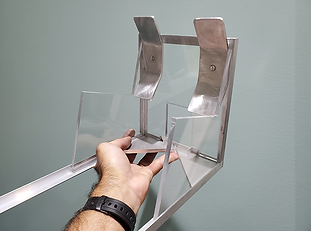
Of course, it is also necessary to create something to hold the ambu while it is being compressed, as well as the linear actuator assembly, which is shown in Figure 7.
In this project, I chose to keep the entire assembly in an upright position; therefore, a support system to keep the assembly in a standing position was also handcrafted. Figure 8 shows the set in a vertical position.


Figure 6 - Component to connect to the movable block to push the ambu
Figure 7 - Composition to hold the ambu and the actuator assembly
Figure 8 - The whole assembly in upright position
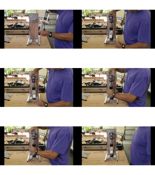
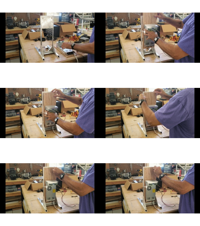
The animations below show the manual mounting of the device. The first shows the mounting of the actuator/motor assembly and the second shows the mounting of the respective power supply and control driver.


The Theory Behind
The linear displacement of the actuator is proportional to the number of steps performed by the stepper motor. Whenever the motor moves clockwise, the actuator advances. Whenever the motor moves steps counterclockwise, the actuator moves backwards.
The frequency with which the actuator moves back and forth is the same as the motor rotating clockwise and counterclockwise.
The actuator speed is directly proportional to the motor speed (steps per second - sps).
With the software library used in this project, the parameters that can be controlled for the stepper motor are: Rotation (in steps), speed (in steps per second) and pause between cycles (seconds)
Considering that turning the motor clockwise (CW) moves the actuator forward, and turning the motor counterclockwise (CCW) moves the actuator backwards, the rotation of the actuator motor going forward can be defined as:
RCW = TV * Ktvd * Kdr (1)
Where:
- TV is the desired Tidal Volume (ml) specified by the user.
- Ktvd is a factor to convert Tidal Volume (TV) to horizontal displacement of the actuator, obtained by calibration.
- Kdr is a factor to convert horizontal displacement of this actuator to rotary steps for the motor, obtained from the actuator’s manufacturer or by calibration.
During a cycle, the actuator must return to the original position where the cycle begun, so:
RCCW = - RCW (2)
The motor velocity (in steps per second) while the actuator goes forward can be defined as:
VCW = RCW / (AFT * Kdr) (3)
Where AFT is the time the actuator takes to move forward.
Here is an important simplification for the present model: Currently, this prototype does not have the capability to perform an “end-inspiratory-hold” (see “Plateu Pressure” in the Fundamentals session). Therefore, in this prototype, AFT is exactly the Inspiratory Time (IT).
That said, replacing AFT with IT, the equation (3) can be written as following:
VCW = RCW / (IT * Kdr) (4)
Similarly, the motor velocity when the actuator goes backward can be defined as:
VCCW = RCCW / (ABT * Kdr) (5)
Where ABT is the time that the actuator moves back to the original position.
However, while AFT is exactly the Inspiration Time, the ABT does not necessarily have to be the Expiration Time (ET). This is due to the characteristics of this project (the ET is not controllable, as It is my understanding that the Expiratory Time (ET) can be considered the time “allocated” for the patient to spontaneously exhale before another cycle begins).
In this case, the Expiratory Time (ET) can be defined as the difference between the duration of each cycle (60/RR) and the Inspiratory Time (IT). In other words, we could say that the time during a cycle that is not Inspiratory Time is Expiratory Time.
ET = (60/RR) – IT (6)
Finally, the pause of the motor between cycles (which is the third motor control parameter) can be defined as:
Pausemotor = ET – ABT (7)
Actuator Backward Time (ABT) is set to a constant in this project. This constant is based on the shortest possible time the actuator is mechanically capable of moving back with maximum displacement. In other words: As soon as the actuator reaches the desired position, it returns to the original position as quickly as possible.
Finally, replacing ET by equation (6), the pause of the motor between cycles can finally be written:
Pausemotor = [(60/RR) – IT] – ABT (8)
Plumbing Circuit
The main character of this project is the ambu-bag, also called BVM (Bag Valve Mask). The ambu is a portable device commonly used to provide positive pressure ventilation to patients who do not breathe or do not breathe properly. The device is a necessary part of resuscitation kits for professionals trained in out-of-hospital settings (such as ambulance teams) and is also often used in hospitals as part of the standard equipment found in emergency rooms. A typical ambu bag was shown in Figure 4, at the top of this page.
The back of an ambu bag (shown to the right of Figure 4) is where the ambient air enters and also where connections for adding O2 are located.
The front of an ambu bag (shown on the left in Figure 4) is where fresh air exits the ambu towards a face mask or endotracheal tube. It is also where the exhaled air returns, diverging to an exhaust port.
Ambu bags usually come with a front set that contains a "pop-off valve” and a "Laerdal valve”. The pop-off valve opens whenever the pressure exceeds 60 cm H2O in order to protect the patient's lungs in case of overpressure applied to the ambu (this limit value varies according to the manufacturer). The Laerdal valve is the most important part of the ambu's plumbing and is designed to prevent exhaled air from returning to the ambu. Figure 9 presents the scheme of a typical ambu.

Figure 9 - Scheme of a typical ambu bag
The concept of using ambu bags for the development of portable ventilators requires an important modification: It is necessary to add a hose to the system in order to reach the patient in bed. However, this hose should not be inserted between the front set and the patient, but between the ambu bag and the front set (therefore, the front set must be removed from the ambu).
The reason is that the Laerdal valve should be as close as possible to the patient to minimize the so-called "dead space", which refers to the CO2 accumulated in the circuit on expiration, which could be inhaled again by the patient.
Most ambus come with front sets without a collector connected to the exhaust port of the Laerdal valve. In this case, the exhaust air is released into the environment through the annular region around the connector. Figure 10 shows a front set without a collector and Figure 11 shows a frontal set with a collector.

Figure 10 - Front set without a collector

Figure 11 - Front set with a collector
Front sets without exhaust collector do not serve the purpose of this project, as they do not allow the connection with two important components in this plumbing circuit:
The first is a HEPA filter, shown in Figure 12. Consider that patients with COVID-19 exhale contaminated air that needs to pass through a HEPA filter before being released into the environment, so as not to contaminate people in the room.
The second is a PEEP valve, shown in Figure 13, whose function has already been explained on the “Fundamentals” page.
A valuable tip is to buy an ambu bag whose front set already comes with the referred exhaust collector, so that the HEPA filter and the PEEP valve can be installed without problems. (see the “list of components” on the project page).
In the two-way door, before connecting to the endotracheal tube (or face mask), there are two more components that will be connected in series: one is a flow meter, shown in Figure 14, and the other is a connector with a small deviation to attach the pressure sensor, shown in Figure 15.

Figure 12 - HEPA filter

Figure 13 - PEEP valve

Figure 14 - Flow meter

Figure 15 - Connector to attach the pressure sensor
Figure 16 presents a scheme for the complete plumbing circuit and Figure 17 shows a photo of this circuit in the current project.

Figure 16 - Complete plumbing circuit scheme

Figure 17 - Complete plumbing circuit photo